
- L298N MOTOR DRIVER CONTROL RGB LEDS HOW TO
- L298N MOTOR DRIVER CONTROL RGB LEDS FULL
- L298N MOTOR DRIVER CONTROL RGB LEDS PRO
- L298N MOTOR DRIVER CONTROL RGB LEDS CODE
Most tutorials on the internet disregard the En pins when teaching how to wire up stepper motors, which is a solution that will only work if your battery source is tailored to the stepper motor you are using./* * Created by ArduinoGetStarted. Well connect an RGB LED to the Arduino Uno and compose a simple program to change its color. Yeap that's the answer I came up with based on my experimentation with this motor driver. RGB LED Color Mixing With Arduino in Tinkercad: Lets learn how to control multi color LEDs using Arduino’s analog outputs. Maybe an electronics expert could shed some light on this?

Note 2: I use "power" in my answer because I am not sure whether the voltage or current is at fault here. So a value lower would reduce power to the stepper and prevent overheating.
L298N MOTOR DRIVER CONTROL RGB LEDS FULL
Note 1: Maximum value for analogWrite is 255, which is equivalent to attaching the jumpers back onto EnA and EnB pins, which means full power from the battery is being supplied to the stepper. In the Arduino Code, I used analogWrite for the pins and adjusted the written value (should be around 50-200 depending on power source and stepper motor specs) until the power supplied to the stepper is just right so it can rotate over a long time without the driver overheating). I connected two Arduino Pins with PWM functionality (Eg 45 and 46 on the Arduino Mega) to EnA and EnB. In this tutorial we will learn how to control individually addressable RGB LEDs or a WS2812B LED strip using Arduino. I tried removing it and the entire chip would not function at all.Ģ) I took out the jumpers from PWM pins EnA and EnB. on the chip, contrary to instructions online that indicated that is should be removed if supplying >12V. Essentially, the solution is to use the EnA and EnB pins to control the power going to the stepper.ġ) I kept the 12V Jumper ( Labelled number 3 in. the brightness of certain lighting projects such as high powered LED arrays. Apparently the battery was supplying too much power to the driver and after awhile, the steppers will stall, probably due to the chip overheating. Materials needed: L298N Dual H-Bridge Motor Controller module (various. I got the same problem supplying 12V to power my stepper motor. *Built-in 5v power supply, when the driving voltage is 7v-35v

Logical current: 0-36mA Drive current: 2A (MAX single bridge).Logical voltage: 5V Drive voltage: 5V-35V.EnB: Enables PWM signal for Motor B (Please see the "Arduino Sketch Considerations" section).

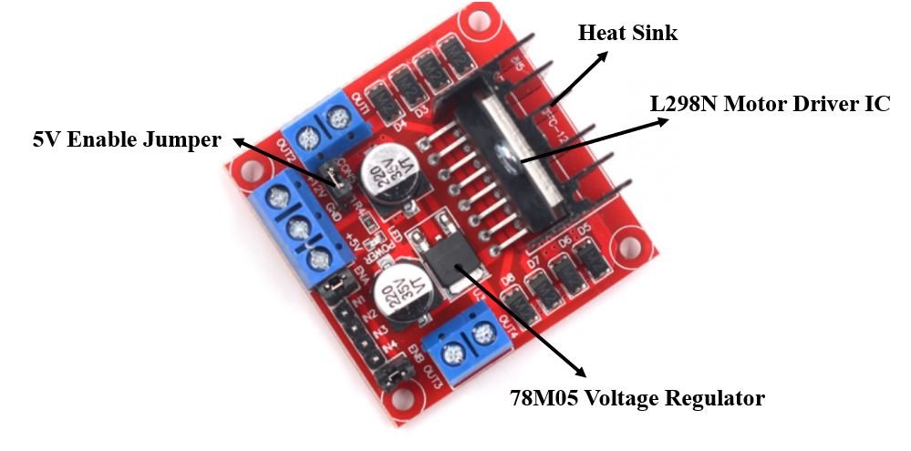
It uses the popular L298 motor driver IC and has the onboard 5V regulator which it can supply to an external circuit. EnA: Enables PWM signal for Motor A (Please see the "Arduino Sketch Considerations" section) This L298 Based Motor Driver Module is a high power motor driver perfect for driving DC Motors and Stepper Motors.5v: 5v input ( unnecessary if your power source is 7v-35v, if the power source is 7v-35v then it can act as a 5v out).Out 4: Mo ( Can actually be from 5v-35v, just marked as 12v).Motors will last much longer and be more reliable if controlled through PWM. The longer the pulses the faster the wheel will turn, the shorter the pulses, the slower the water wheel will turn. SKU: A100010011 Categories: Motor Driver, Robotics and CNC Tags: DC Motor Driver, Stepper Motor Driver. L298N Dual H-Bridge 3A Motor Driver Board quantity. Pre-assembled L298N Dual Motor Driver Board, with Led indicators, an on board +5V regulator and protection diodes. Take the water wheel analogy and think of the water hitting it in pulses but at a constant flow. L298N Dual H-Bridge 3A Motor Driver Board.
L298N MOTOR DRIVER CONTROL RGB LEDS PRO
four digit LCD Tower Pro MG90S: servo motors LEDs (single color and RGB).
L298N MOTOR DRIVER CONTROL RGB LEDS CODE
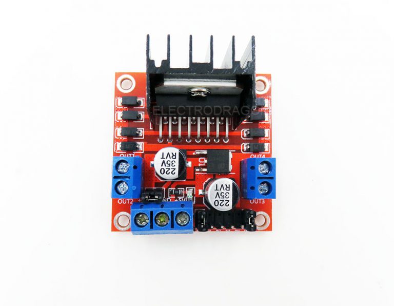
Motors are rated at certain voltages and can be damaged if the voltage is applied to heavily or if it is dropped quickly to slow the motor down. For the ones that have a particular controller chip, I have added the code of. The voltage would be the water flowing over the wheel at a constant rate, the more water flowing the higher the voltage. The L298N motor driver module consists of a L298N motor driver IC ,78M05 5V regulator, 5V jumper enable, power LED, heat sink, resistors and capacitors all. In motors try to imagine the brush as a water wheel and electrons as a the flowing droplets of water. * Pulse Width Modulation is a means in controlling the duration of an electronic pulse. H-Bridge's are typically used in controlling motors speed and direction, but can be used for other projects such as driving the brightness of certain lighting projects such as high powered LED arrays.Īn H-Bridge is a circuit that can drive a current in either polarity and be controlled by *Pulse Width Modulation (PWM).


 0 kommentar(er)
